Understanding Shell Type Transformers
You often come across transformers in power supplies and control systems, but understanding how a shell type transformer works can make things much clearer. In this guide, you’ll explore its structure, winding arrangement, cooling methods, and practical uses in simple terms. You’ll see how the core surrounds the windings, how magnetic flux moves inside, and how this design compares with core type transformers. By the end, you’ll have a clear picture of when and why this transformer type is used.Catalog
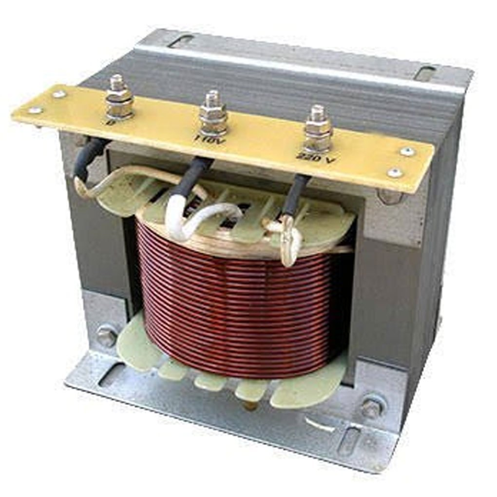
Figure 1. Shell Type Transformer Structure
What Is a Shell Type Transformer
A shell type transformer is a transformer classified by its core construction, in which the magnetic core surrounds a large portion of the windings. In this design, the primary and secondary windings are placed on a central limb, while the surrounding core material encloses them from both sides. This arrangement creates a compact structure where the magnetic material partially wraps around the coils, which is why it is described as a shell form.
The transformer operates on the principle of electromagnetic induction. When alternating current flows through the primary winding, it produces a changing magnetic field within the core. This varying magnetic field links with the secondary winding and induces a voltage across it, allowing electrical energy to transfer from one circuit to another while maintaining electrical isolation between them.
What defines a shell type transformer is this core-surrounding-winding configuration, which sets it apart from other transformer constructions that use a different physical layout. The classification is based strictly on structural design, since the fundamental electrical function remains the same as in other transformers that rely on induction for voltage transformation.
Construction of a Shell Type Transformer
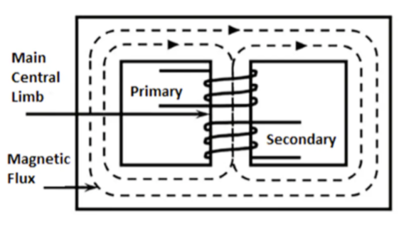
Figure 2. Shell Type Transformer Core Construction
The construction of a shell type transformer is based on the arrangement of its laminated steel core and centrally placed windings. The core is formed from thin insulated E and I shaped laminations stacked together to create a compact and mechanically strong structure that reduces internal losses.
Both the primary and secondary windings are positioned on the central limb of the core. The remaining portions of the core surround the windings on both sides, forming a rigid enclosure. This arrangement provides strong mechanical support and helps protect the windings from external forces. Careful clamping and alignment of laminations are used in modern construction to maintain tight structural integrity and consistent magnetic performance.
Core Structure and Limb Arrangement
A single phase shell type transformer core consists of three limbs. The central limb carries the entire magnetic flux, while each of the two outer limbs carries half of that flux. Because the full magnetic flux passes through the central limb before dividing, it is designed with a larger cross sectional area, typically about twice that of each outer limb. This proportional sizing maintains uniform magnetic flux density within the core material.
The three limb arrangement forms two closed magnetic paths inside the core. This configuration enhances mechanical strength and ensures firm structural support around the windings placed on the central limb.
Magnetic Flux Path
Magnetic flux travels through the central limb and then divides into two separate paths along the outer limbs. These paths reconnect through the top and bottom yokes, completing the magnetic circuit. The presence of two return paths allows the magnetic field to distribute evenly through the core material.
This controlled internal flux route confines the magnetic field within the core and minimizes stray magnetic fields outside the structure. The symmetrical layout supports stable magnetic flow within the core assembly.
How a Shell Type Transformer Works
A shell type transformer operates on the principle of electromagnetic induction. When an alternating voltage is applied to the primary winding, alternating current flows through it and produces a continuously changing magnetic field within the core. As the current changes in magnitude and direction, the magnetic field also varies accordingly.
This varying magnetic field creates a changing magnetic flux in the core, which links with the secondary winding. According to Faraday’s law, a changing flux induces a voltage in the secondary winding. The magnitude of this induced voltage depends on the ratio of turns between the primary and secondary windings, allowing energy to transfer from the primary circuit to the secondary circuit without direct electrical contact.
In the shell type design, the magnetic flux divides into two internal paths as it moves through the core before completing its circuit. These parallel paths allow the flux to spread more evenly within the magnetic material. By maintaining a balanced internal flow of flux, the design confines the magnetic field within the core and reduces stray magnetic effects, supporting stable and efficient operation.
Winding Arrangement in a Shell Type Transformer
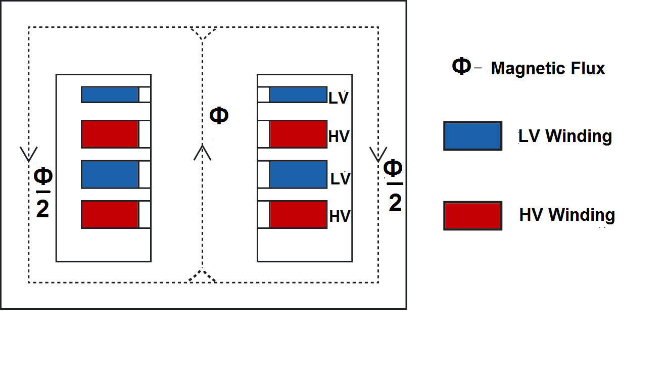
Figure 3. Shell Type Transformer Winding Arrangement
In a shell type transformer, the high voltage and low voltage windings are installed on the central limb and arranged concentrically. The low voltage winding is generally placed nearest to the core, while the high voltage winding is wound over it. This positioning helps control insulation requirements between the core and the higher potential winding while keeping the overall structure compact.
The windings are typically divided into several sections and arranged in a sandwich or interleaved configuration. In this arrangement, sections of the high voltage winding alternate with sections of the low voltage winding along the length of the limb. This layered structure keeps the windings closely aligned and promotes effective magnetic interaction between them.
Because the winding sections are placed in close proximity, proper insulation is required between adjacent layers to maintain electrical separation under operating voltage conditions. The layered configuration also affects servicing, as access to inner winding sections may require removal of outer layers.
Cooling Methods in Shell Type Transformers
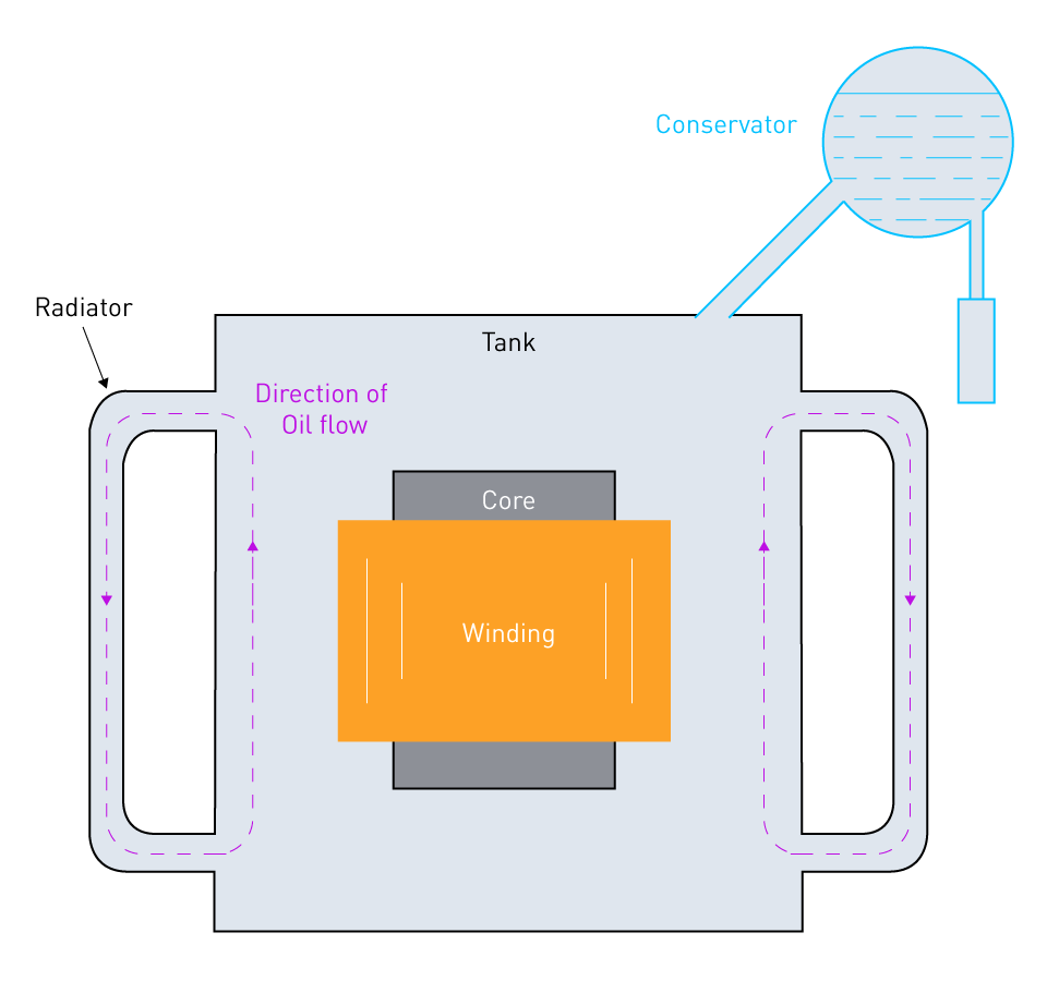
Figure 4. Shell Type Transformer Oil Cooling System
Heat is produced in the windings during operation because electrical current flows through conductors that have resistance. If this heat accumulates, the temperature of the windings and insulating materials can rise to levels that affect safe operation. For this reason, effective cooling is necessary to keep temperatures within specified limits.
In shell type transformers, the active parts are enclosed within a tank, which limits direct exposure to surrounding air. This enclosure restricts natural heat dissipation, making additional cooling arrangements necessary in many applications.
A common method is oil cooling, where insulating oil surrounds the core and windings inside the tank. The oil absorbs heat and circulates naturally due to temperature differences. As indicated in the diagram, warm oil rises toward radiator sections attached to the tank, releases heat to the surrounding air, and then returns downward after cooling. This continuous circulation supports steady heat removal.
In applications requiring greater thermal control, forced air cooling may be applied. Fans increase airflow over the tank or radiator surfaces, improving heat transfer to the environment. For higher power ratings, systems may also use controlled oil circulation to enhance internal heat movement.
Maintaining proper cooling conditions helps ensure that operating temperatures remain within design limits and supports reliable transformer performance under load.
Advantages and Disadvantages of Shell Type Transformers
| Advantages | Limitations |
| High mechanical strength under short-circuit conditions | More complex core and winding construction |
| Reduced leakage flux due to close winding coupling | Higher insulation requirements between winding sections |
| Compact and rigid structure | More difficult access to inner windings for maintenance |
| Better protection of windings within the core | Increased manufacturing cost |
| Efficient magnetic flux distribution through two parallel paths | Heavier core structure due to additional steel |
| Lower leakage reactance | Cooling can be less effective without forced methods |
| Improved voltage regulation characteristics | Not as suitable for very high voltage ratings |
| Reduced conductor length in certain winding arrangements | Assembly requires precise lamination stacking |
| Strong resistance to mechanical vibration | Repair work often requires partial dismantling |
| Stable performance under load variations | Larger material usage compared to simpler core designs |
Applications of Shell Type Transformers
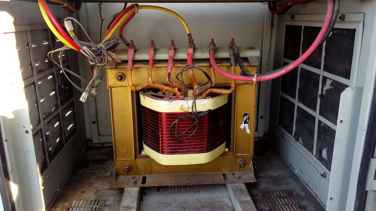
Figure 5. Shell Type Transformer Low Voltage Application
Shell type transformers are widely used in low voltage applications that require dependable voltage conversion. They are commonly installed in electronic equipment, control circuits, and instrumentation systems operating at moderate power levels. Their structure allows them to fit efficiently within enclosed assemblies such as control panels and electrical cabinets, where space must be used carefully.
They are also applied in power supply units for industrial and commercial equipment. In these systems, the transformer adjusts voltage levels to meet the requirements of connected devices. Typical examples include battery chargers, laboratory instruments, communication systems, and audio equipment, where stable voltage transformation is essential for proper operation.
In addition, shell type transformers are used in machinery exposed to mechanical stress. Their rigid construction makes them suitable for welding equipment, traction systems, and various industrial machines that demand structural stability during service. The compact form further supports installation in equipment with limited internal space, making them practical for densely arranged electrical systems.
Shell Type vs Core Type Transformer Comparison
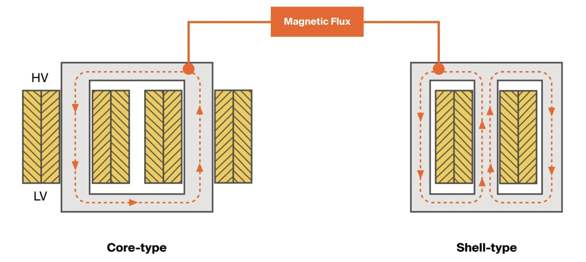
Figure 6. Shell Type vs Core Type Transformer Comparison
Shell type and core type transformers differ primarily in their core structure and winding placement. In a core type transformer, the magnetic core typically has two main limbs, with windings arranged around those limbs. In a shell type transformer, the core is formed with three limbs, and both windings are placed on the central limb, enclosed by the surrounding core material. This structural distinction defines the overall layout of each design.
The magnetic flux path also varies. In a core type transformer, the flux generally follows a single closed path through the core. In a shell type transformer, the flux divides into two parallel paths before completing the magnetic circuit, as reflected in the comparison diagram. This difference affects how magnetic forces are distributed within the core.
Winding distribution follows the same pattern. Core type transformers position windings on separate limbs, while shell type transformers concentrate them on one central limb. These structural differences influence mechanical and cooling characteristics. Shell type transformers provide stronger mechanical support because the windings are enclosed by the core on both sides, whereas core type transformers offer easier physical access to windings and typically allow more direct exposure for cooling.
Conclusion
Shell type transformers are defined by how the core surrounds the windings, creating a compact and mechanically strong structure. You’ve seen how the laminated core is arranged, how magnetic flux moves through two internal paths, and how voltage is transferred through electromagnetic induction. The winding layout and cooling methods support stable operation under load. You also explored the advantages, limitations, and practical applications of this design. With this understanding, you can better decide when a shell type transformer is suitable compared to a core type transformer.
עלינו
ALLELCO LIMITED
קרא עוד
חקירה מהירה
אנא שלח בירור, נגיב מייד.
שאלות נפוצות [FAQ]
1. What makes a shell type transformer different from a core type transformer?
A shell type transformer has a core that surrounds the windings on both sides, while a core type transformer has windings placed around the core limbs.
2. Why does a shell type transformer have three limbs?
It uses three limbs so the magnetic flux can divide into two paths inside the core, helping distribute magnetic forces evenly.
3. Where are shell type transformers commonly used?
They are commonly used in low to medium voltage applications such as power supplies, control panels, and electronic equipment.
4. Why is cooling important in shell type transformers?
Cooling removes heat generated in the windings and helps keep the transformer operating within safe temperature limits.
5. What is the advantage of the sandwich winding arrangement?
The sandwich arrangement improves magnetic coupling between windings and helps maintain compact construction.
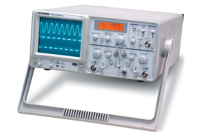
אוסילוסקופ אנלוגי: איך זה עובד, חלקים, סוגים ושימושים
ב- 2026/02/12

עיבוד אותות דיגיטלי (DSP): איך זה עובד, רכיבים, טכניקות ויישומים
ב- 2026/02/11
פוסטים פופולריים
-
מחשבים מערכי הוראות מורכבים: כיצד הם שינו מחשוב?
ב- 8000/04/18 147760
-
Pinout USB-C ותכונות
ב- 2000/04/18 111974
-
שימוש בפרימיטיביות סימולציה אחידות של Xilinx: מדריך מקיף לעיצוב וסימולציה של FPGA
ב- 1600/04/18 111351
-
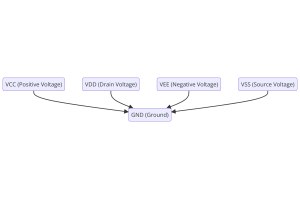
מתחי אספקת חשמל באלקטרוניקה: המשמעות של VCC, VDD, VEE, VSS ו-GND
ב- 0400/04/18 83742
-

מדריך מחברים RJ45: Pinout, חיווט, סוגי כבלים ושימושים
ב- 1970/01/1 79527
-
המדריך האולטימטיבי לקודי צבע חוט במערכות חשמל מודרניות
האופן בו מערכות החשמל שלנו משתמשות בצבעים אינן רק למראה.כל צבע חוט מציין כעת פונקציה ספציפית, מה שמקל על זיהוי וטיפול נכון ברכיבים חשמליים במהלך ההתקנה והתחזוקה.זה לא רק מזרז תהליכים תפעוליים אלא ג...ב- 1970/01/1 66937
-
מדריך שסתומי טיהור: תפקוד, תסמינים, בדיקה והחלפה לביצועי מנוע מיטביים
שסתום הטיהור הוא חלק מרכזי במערכת המכונית המסייעת לשמור על נקייה של האוויר על ידי ניהול אדי דלק לפני שהם יכולים לברוח לאטמוספרה.זה לא רק מסייע לסביבה על ידי הפחתת הזיהום, אלא גם משפר את המכונית ומש...ב- 1970/01/1 63086
-

גורם איכותי (ש) גורם: משוואות ויישומים
גורם האיכות, או 'Q', חשוב בבדיקת עד כמה משרנים ומהודדים עובדים במערכות אלקטרוניות המשתמשות בתדרי רדיו (RF).'Q' מודד עד כמה מעגל מצמצם את אובדן האנרגיה ומשפיע על טווח התדרים שהמערכת יכולה להתמודד עם...ב- 1970/01/1 63025
-
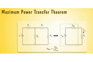
השגת ביצועי שיא עם משפט העברת הכוח המרבי
משפט העברת הכוח המרבי מסביר כיצד אנרגיה ממקור, כמו סוללה או גנרטור, זורמת לעומס מחובר.זה מראה את התנאי המדויק בו העומס מקבל הכי הרבה כוח.מאמר זה מכסה את המשמעות של משפט, כיצד הוא עובד במעגלי DC וגם...ב- 1970/01/1 54092
-
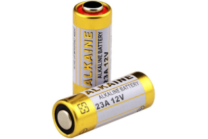
מפרטי סוללה A23 ותאימות
סוללת A23 היא סוללה קטנה בצורת צילינדר עם מתח גבוה.נקרא גם 23A, 23AE או MN21, הוא פועל ב 12 וולט וגבוה בהרבה מסוללות AA או AAA.העיצוב המיוחד שלו הופך אותו למושלם לגאדג'טים הזקוקים למקור כו...ב- 1970/01/1 52167
מספר חלק חם
-
AD9410BSVZ
Analog Devices Inc.
IC ADC 10BIT PIPELINED 80TQFP
TLV2451CD
Texas Instruments
IC OPAMP GP 1 CIRCUIT 8SOIC
AP1084K25L-13
Diodes Incorporated
IC REG LINEAR 2.5V 5A TO263-2
DTA115EETL
Rohm Semiconductor
TRANS PREBIAS PNP 150MW EMT3
S9S08AW32E5MFGE
Freescale Semiconductor
IC MCU 8BIT 32KB FLASH 44LQFP
CYDMX128B16-65BVXI
Infineon Technologies
IC SRAM 128KBIT PAR 100VFBGA
TMK063CG100DT-F
Taiyo Yuden
CAP CER 10PF 25V C0G/NP0 0201
SY100EL32VZG
Microchip Technology
IC DIVIDER BY 2 1-BIT 8SOIC
AQY282EH
Panasonic Electric Works
SSR RELAY SPST-NO 500MA 0-60V
HCNW135
Avago Technologies (Broadcom Limited)
OPTOISO 5KV TRANS W/BASE 8DIP
GRM3196T2A6R0DD01D
Murata Electronics
CAP CER 6PF 100V T2H 1206
CSD68815W15
Texas Instruments
PROTOTYPE
MC20XS4200FK
NXP USA Inc.
IC PWR SWITCH N-CHAN 1:1 23PQFN
LTC1735CS#PBF
Analog Devices Inc.
IC REG CTRLR BUCK 16SOIC
ISL6545CBZ
Renesas Electronics America Inc
IC REG CTRLR BUCK 8SOIC
LT1167AIN8#PBF
Analog Devices Inc.
IC INST AMP 1 CIRCUIT 8DIP
MBR40250G
onsemi
DIODE SCHOTTKY 250V 40A TO220-2
SY89544UMG-TR
Microchip Technology
IC MULTIPLEXER 1 X 4:1 32MLF -
HCPL-263L#500
Broadcom Limited
OPTOISO 3.75KV OPEN COLL 8DIP GW
RT0603BRE07150KL
YAGEO
RES SMD 150K OHM 0.1% 1/10W 0603
MPQ3367GR-AEC1-Z
Monolithic Power Systems Inc.
6 CHANNELS, MAX.150MA/CH,BOOST W
S9S12G64F0CLH
NXP USA Inc.
IC MCU 16BIT 64KB FLASH 64LQFP
TMK063CG330JT-F
Taiyo Yuden
CAP CER 33PF 25V C0G/NP0 0201
800B6R8CT500XT
American Technical Ceramics
CAP CER 6.8PF 500V C0G/NP0 1111
AD8532ARUZ
Analog Devices Inc.
IC OPAMP GP 2 CIRCUIT 8TSSOP
TLZ11C-GS08
Vishay General Semiconductor - Diodes Division
DIODE ZENER 11V 500MW SOD80
VI-J3Z-01
Vicor Corporation
VI-J3Z-01 48V/2V 20A
1N6270A
onsemi
TRANS VOLTAGE SUPPRESSOR DIODE
TS5V522CDBQR
Texas Instruments
IC VGA SWITCH 5BIT 24SSOP
DM74ALS174MX
Fairchild Semiconductor
IC FF D-TYPE SNGL 6BIT 16SOIC
SDM100K30L-7
Diodes Incorporated
DIODE SCHOTTKY 30V 1A SOD323
MAX1722EZK-T
Analog Devices Inc./Maxim Integrated
STEP-UP DC-DC CONVERTER
FNA40860B2
Fairchild Semiconductor
AC MOTOR CONTROLLER, 16A
BC846ASQ-7-F
Diodes Incorporated
GENERAL PURPOSE TRANSISTOR SOT36
DRV5011ADDMRT
Texas Instruments
MAGNETIC SWITCH LATCH 4X2SON
5V41235PGGI
Renesas Electronics America Inc
IC CLK GEN SPRED SPECTRM 16TSSOP -

VS-8EWS10STRL-M3
Vishay General Semiconductor - Diodes Division
DIODE GEN PURP 1KV 8A DPAK
VLF4012AT-4R7M1R1
TDK Corporation
FIXED IND 4.7UH 1.1A 160MOHM SMD
VI-LCWY-EW
Vicor Corporation
DC/DC CONVERTER 24V 3.3V
GRM1555C1E8R0CA01D
Murata Electronics
CAP CER 8PF 25V C0G/NP0 0402
GCM188R71E472KA37D
Murata Electronics
CAP CER 4700PF 25V X7R 0603
XRT7296IW-F
MaxLinear, Inc.
IC DRIVER 28SOJ
NCP1238AD65R2G
onsemi
IC OFFLINE SWITCH FLYBACK 7SOIC
BZD27C6V2P
Rectron USA
DIODE ZENER 6.2V 800MW SOD-123F
MKP1848S63050JY5C
Vishay Beyschlag/Draloric/BC Components
CAP FILM 30UF 5% 500VDC RADIAL
SN65LBC176DR
Texas Instruments
IC TRANSCEIVER HALF 1/1 8SOIC
MAX5027EUT+T
Analog Devices Inc./Maxim Integrated
IC REG BOOST 30V 260MA SOT23-6
SFF1008G
Taiwan Semiconductor Corporation
DIODE GEN PURP 600V 10A ITO220AB
SHLP-08V-S-B
JST Sales America Inc.
CONN RCPT HSG 8POS 1.00MM
TS462CPT
STMicroelectronics
IC OPAMP GP 2 CIRCUIT 8TSSOP
PIC16C926-I/PT
Microchip Technology
IC MCU 8BIT 14KB OTP 64TQFP
AH5775-P-B
Diodes Incorporated
IC MOTOR DRIVER 2.5V-18V TO94
1N4589
Solid State Inc.
DIODE GEN PURP 300V 150A DO8
LT6654AHS6-4.096#TRMPBF
Analog Devices Inc.
IC VREF SERIES 0.05% TSOT23-6